Week 19, Project Development
This week assignment tasks are
a) to complete your final project
When is the deadline and time left?
What are the task completed?
1. PCB completed
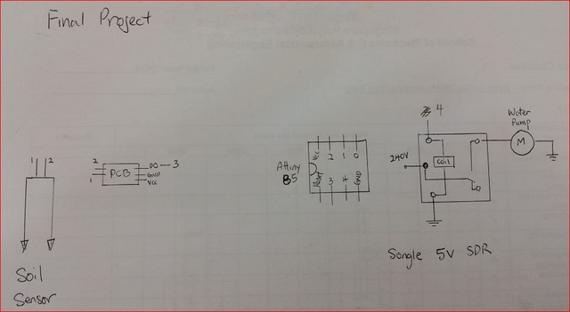
Circuit Sketch Up
Follow up by hooking up the circuit on a test board to test out the circuit with a small 5VDC motor; simulated as water pump; for errors first.
Then translated into a cad file using EagleCAD.
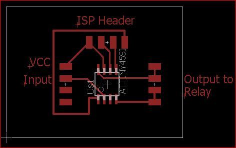
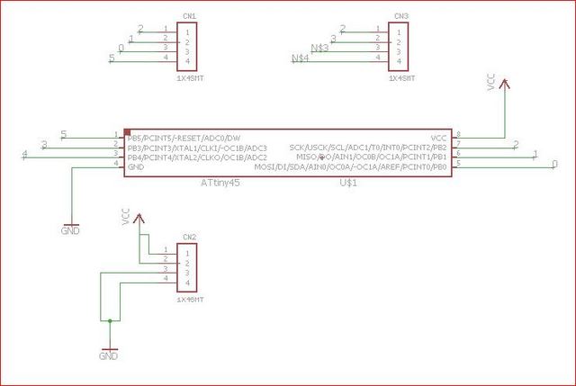
Final Project Board (Right click and save link as) Final Project Schematic (Right click and save link as)
After going through the PCB miller
Now is to test the PCB by hooking up as shown below.
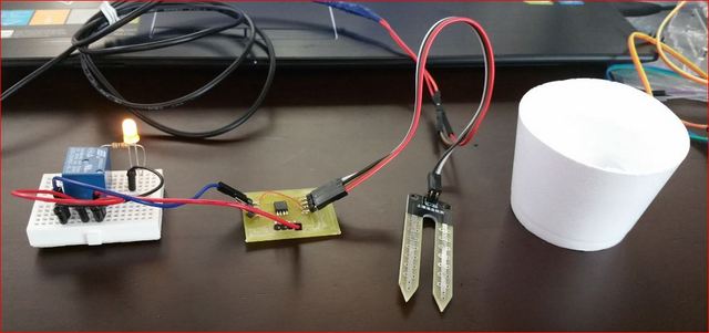
When soil sensor is dry, the output LED is lighted up.
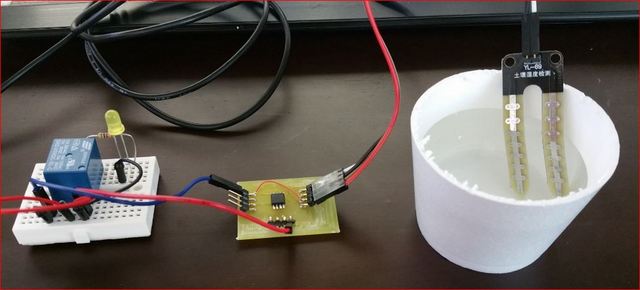
When soil sensor is wet, the output LED is lights off.
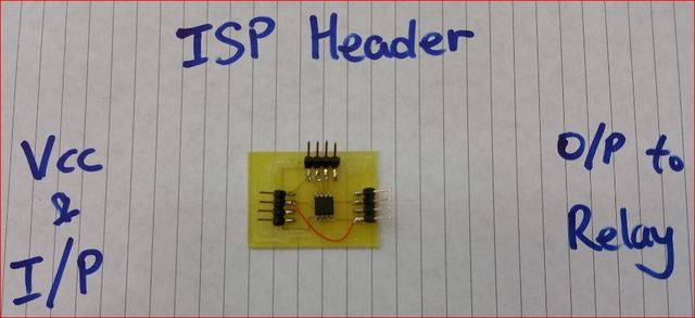
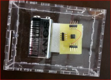
Proceeded to produce a PCB and soldered the components onto it.
View the video on the circuit testing with the sensor as input and output to a 5VDC motor. The 5VDC motor was used as a substitute to simulate a submersible pump.
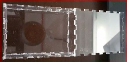
2. Housing completed
I measured the housing dimensions and went to this website Make A Box to print out design in PDF.
After which I used Coraldraw to laser cut out the housing.
The files can be download here Housing in PDF and Laser Cut Box
3. 3D Printing the soil sensor tab

Therefore decided to design one to suit my needs. Did a simple measurement and used AutoCAD to draw the design and save as .stl file.
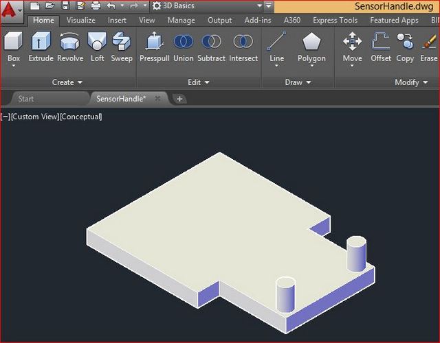
Sensor Handle (Right click and save link as)
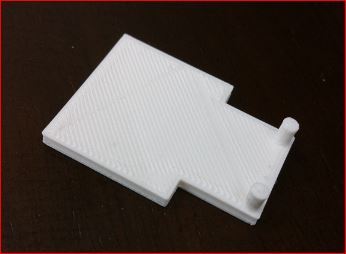
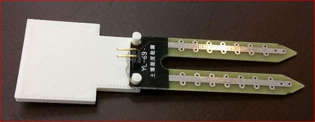
Following that I used Cubicon 3D printer to print out the design and fit it unto the sensor.
Things that worked and hasn't
After the presentation, I found time and continued to mill a new PCB and got it work finally.
The Results and Improvement
My comments
What needs to be resolved?
The frustrating part is milling the PCB. It kept shorting out when doing the conductivity test. Therefore, I kept having to do the PCB milling, it was really a time, cost and material waster. Probably a better PCB miller should be invested for SMD components. I already lost count the number of PCB that failed just by doing this final project. Not to mention the components that were destroyed in the process of desoldering.What have I learned?
I have learned to push limits of my patience and handled the whole lot of frustration.